
There are 12 butotns in IR Remote, so in this project we just use eight of them to controlling the relays. Button 1 to 4 is to turn on Relay 1 to 4, while button 5 to 8 is use to turn off Relay 1 to 4. LCD is used to display the pressed button data. Relay as an actuator that will directly control the electric, with Alternate Current especially.
Hardware Requirement
- Relay Module 5V with 4 Channel
- Arduino UNO
- Xinda IR Remote Control Kit
- LCD 2x16
- Power supply +5 Volt
- Jumper Cable


Block Diagram

Schematic
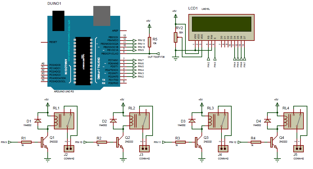
Arduino - LCD Wiring

Arduino - IR Remote Receiver Wiring

Arduino - Relay Wiring

Source Code/Sketch
#include <IRremote.h>
#include <LiquidCrystal.h>
LiquidCrystal lcd(2, 3, 4, 5, 6, 7);
int IR_PIN = 8;
int Rl1 = 9;
int Rl2 = 10;
int Rl3 = 11;
int Rl4 = 12;
IRrecv irrecv(IR_PIN);
decode_results results;
void setup(){
for(char i=9; i<13; i++){
pinMode(i, OUTPUT);
digitalWrite(i, LOW);
}
lcd.begin(16, 2);
lcd.print(" Kontrol 4Relay");
lcd.setCursor(0, 1);
lcd.print(" dg Remot IR");
delay(2000);
irrecv.enableIRIn();
}
void loop(){
lcd.setCursor(0, 1);
lcd.print("Tekan Tb 1 s/d 8");
if (irrecv.decode(&results)){
irrecv.resume();
lcd.setCursor(0,1);
switch(results.value){
case 0xFF30CF: lcd.print("Relay 1 ON ");
digitalWrite(Rl1, HIGH);break;
case 0xFF18E7: lcd.print("Relay 2 ON ");
digitalWrite(Rl2, HIGH);break;
case 0xFF7A85: lcd.print("Relay 3 ON ");
digitalWrite(Rl3, HIGH);break;
case 0xFF10EF: lcd.print("Relay 4 ON ");
digitalWrite(Rl4, HIGH);break;
case 0xFF38C7: lcd.print("Relay 1 OFF ");
digitalWrite(Rl1, LOW);break;
case 0xFF5AA5: lcd.print("Relay 2 OFF ");
digitalWrite(Rl2, LOW);break;
case 0xFF42BD: lcd.print("Relay 3 OFF ");
digitalWrite(Rl3, LOW);break;
case 0xFF4AB5: lcd.print("Relay 4 OFF ");
digitalWrite(Rl4, LOW);break;
case 0xFF6897: lcd.print("Relay All ON ");
digitalWrite(Rl1, HIGH);
digitalWrite(Rl2, HIGH);
digitalWrite(Rl3, HIGH);
digitalWrite(Rl4, HIGH);break;
case 0xFF52AD: lcd.print("Relay All OFF ");
digitalWrite(Rl1, LOW);
digitalWrite(Rl2, LOW);
digitalWrite(Rl3, LOW);
digitalWrite(Rl4, LOW);break;
}
delay(2000);
}
}
How it Works
1. Connect the Arduino with Peripherals needed
2. Plug in the Power Source on the device
3. Compile and upload the script program above to your arduino
2. Plug in the Power Source on the device
3. Compile and upload the script program above to your arduino
4. Initial Display on LCD


6. Then press the button on the remote, for example Power button is pressed then on the LCD will
display

7.Button 1 is pressed then relay 1 ON and on LCD will display

8. The next keystroke will be responded after 2 seconds and the LCD returns to normal view.
Video for Project III - 12. Controlling 4 Channel Relay using IR Remote (Arduino Based)
Required File

No comments:
Post a Comment