
Thermostat using 7 Segment Display


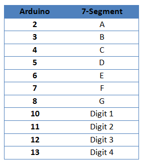
Arduino - 7 Segment Wiring

Arduino - LM35 Wiring

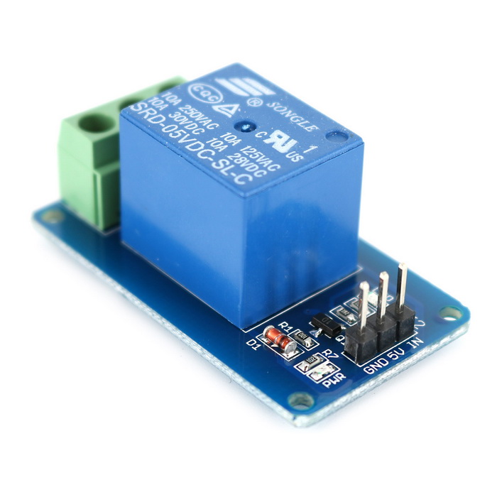
Arduino - Relay Wiring

Arduino - Buttons Wiring

How it Works
1. Connect the Arduino with Peripherals needed.
2. Plug in the Power Source on the device.


Thermostat is a tool used to maintain the temperature in accordance with the set point that has been determined. The temperature is read by the LM35 sensor and the results are displayed on seven segments. Seven segment consists of 4 digits, 2 digits to display the readable temperature and 2 digits to display the unit degree celsius. While set point in setting by using 3 button. The SET button is used to enter in the set point set menu. UP button used to add / raise setpoint. While the DOWN button is used to reduce the setpoint. The heater / controller in its ON / OFF control uses a relay connected to the output leg of the Arduino.
Hardware Requirement
- Arduino Uno Board
- LM35 Module
- 4 Digit of 7-Segment with Common Anode
- Relay 1 Channel Module
- 3 Push Button
- Power supply +5 Volt
- Jumper


Element Heater | Source
Block Diagram

Schematic


Arduino - 7 Segment Wiring
Arduino - LM35 Wiring

Arduino - Relay Wiring
Source Code/Sketch
int adc,T,setPoint;
byte setSP, f_awal, kedip;
long lastButton = 0;
long delayAntiBouncing = 50;
byte seven_seg_digits[12][7] = { { 0,0,0,0,0,0,1 }, // = 0
{ 1,0,0,1,1,1,1 }, // = 1
{ 0,0,1,0,0,1,0 }, // = 2
{ 0,0,0,0,1,1,0 }, // = 3
{ 1,0,0,1,1,0,0 }, // = 4
{ 0,1,0,0,1,0,0 }, // = 5
{ 0,1,0,0,0,0,0 }, // = 6
{ 0,0,0,1,1,1,1 }, // = 7
{ 0,0,0,0,0,0,0 }, // = 8
{ 0,0,0,0,1,0,0 }, // = 9
{ 0,0,1,1,1,0,0 }, // = derajat
{ 0,1,1,0,0,0,1 } // = C
};
void setup(){
for(char i=2; i<13; i++){
pinMode(i,OUTPUT);
}
pinMode(A1,INPUT);
pinMode(A2,INPUT);
pinMode(A3,INPUT);
digitalWrite(A1,HIGH);
digitalWrite(A2,HIGH);
digitalWrite(A3,HIGH);
pinMode(A4,OUTPUT);
setPoint=40;
}
void loop(){
adc = analogRead(0);
T = (adc*5)/10;
tampilSuhu();
tampilC();
if(T<(setPoint-1) || f_awal==0){
digitalWrite(A4,HIGH);
f_awal=1;
}
else if(T>=setPoint){
digitalWrite(A4,LOW);
}
tombol();
}
void tampilSuhu(){
digitalWrite(10,LOW); digitalWrite(11,HIGH);
digitalWrite(12,HIGH); digitalWrite(13,HIGH);
if (setSP==1){
sevenSegWrite(setPoint/10);
}
else{
sevenSegWrite(T/10);
}
delay(5);
digitalWrite(10,HIGH); digitalWrite(11,LOW);
digitalWrite(12,HIGH); digitalWrite(13,HIGH);
if (setSP==1){
sevenSegWrite(setPoint%10);
}
else{
sevenSegWrite(T%10);
}
delay(5);
}
void tampilC(){
digitalWrite(10,HIGH); digitalWrite(11,HIGH);
digitalWrite(12,LOW); digitalWrite(13,HIGH);
sevenSegWrite(10);
delay(5);
digitalWrite(10,HIGH); digitalWrite(11,HIGH);
digitalWrite(12,HIGH); digitalWrite(13,LOW);
sevenSegWrite(11);
delay(5);
}
void sevenSegWrite(byte segment) {
byte pin = 2;
for (byte segCount = 0; segCount < 7; ++segCount) {
digitalWrite(pin, seven_seg_digits[segment][segCount]);
++pin;
}
}
void tombol(){
if(digitalRead(A1)==0){
if ((millis() - lastButton) > delayAntiBouncing){
setSP=1;
}
lastButton = millis();
}
while (setSP){
//-----------------tombol seting
if(digitalRead(A1)==0){
if ((millis() - lastButton) > delayAntiBouncing){
setSP=0;
}
lastButton = millis();
}
//---------------tombol up
else if(digitalRead(A2)==0){
if ((millis() - lastButton) > delayAntiBouncing){
setPoint++;
}
lastButton = millis();
}
//---------------tombol down
else if(digitalRead(A3)==0){
if ((millis() - lastButton) > delayAntiBouncing){
if (setPoint>0){
setPoint--;
}
}
lastButton = millis();
}
if (kedip<30){
tampilC();
}
else{
tampilSuhu();
tampilC();
if(kedip>60)kedip=0;
}
++kedip;
}
setSP=0;
}
How it Works
1. Connect the Arduino with Peripherals needed.
2. Plug in the Power Source on the device.
3. Add some library if needed
4. Compile and upload the script pr
5. Normal view displays the readable temperature.

6. The heater will be ON when the temperature is below the set point, the initial set point is 40°C.
7. Heater OFF when the temperature is equal to set point.
8. Heater will light up again after the temperature decreases 5° C below the set point.
9. To set the set point by pressing the SET button, so the seven segment displays the setpoint temperature
And flashing.

10. Press UP button to increase set point temperature or press DOWN button to decrease it.
11. Press the SET button when the settings are done.
Video for Project III - 9. Thermostat using 7 Segment Display based On Arduino
Required file


